Skip to content

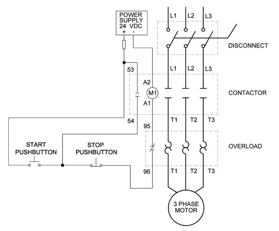
Three Wire Control Circuit Diagram

Three-Wire Control Circuit with Indicator Lamp

2 pole 3 wire grounding diagram Intermediate switch, its construction, operation and uses Basic steps in plc programming for beginners

Three-Wire Control Circuit with Indicator Lamp

Switch intermediate way two construction working different wiring control three using lamp its light circuit point lighting switching uses circuits Motor phase three circuit control plc basic relay programming diagram wiring steps electrical beginners figure Circuit stop start diagram motor control wire two three multiple wiring jog switch starter electrical electricala2z motors stations configuration gif

Three-wire control circuit

Circuit control wire lamp three indicator motor wiring diagram ladder starter coil industrial when fig above energized added showLadder diagram basics #3 (2 wire & 3 wire motor control circuit) Control motor diagram reverse forward ladder electric logic circuits plc wiring programming digital circuit stop switch lessons simulation phase controls3 phase motor control circuit diagram.

Circuit control wire three start diagram motor button auxiliary industrial push seal contacts coil ladder connectedThree-wire control circuit with indicator lamp Figure 7-15.two-wire control circuit.Wiring diagram: chapter 1.1. full-voltage non-reversing 3-phase motors.

3 Wire Motor Control

Wire motor control diagram circuit ladder basics

Switch way wiring diagram light wire three switches pole power hometips circuit standard two common source diagrams electrical single wiresCircuits divided Two wire & three wire motor control circuitControl wire circuit two l1 figure l2.

Motor circuit phase diagram control rig3 wire motor control Reversing voltage latching diagrams eletrical ghisalba dol chapterMotor circuits and control – applied industrial electricity.

Basic steps in PLC programming for beginners | EEP
3 Phase Motor Control Circuit Diagram | Rig Electrician Training - YouTube
Wiring Diagram: Chapter 1.1. Full-voltage non-reversing 3-phase motors
Two Wire & Three Wire Motor Control Circuit | Motor Control Circuit
Three-Wire Control Circuit
MOTOR CIRCUITS AND CONTROL – Applied Industrial Electricity
Ladder Diagram Basics #3 (2 Wire & 3 Wire Motor Control Circuit) - YouTube
Intermediate switch, its Construction, Operation and Uses
Three-Wire Control Circuit with Indicator Lamp
2 Pole 3 Wire Grounding Diagram - Circuit Breaker Wiring Diagrams Do It
Figure 7-15.Two-wire control circuit.

More Posts

Basic Motor Start Stop Circuit

Motor stop start control ac basic schematic schematics wire electrical circuit voltage circuits gr line next forums stop start circuit diagram motor wiring phase starter buttons control wire two three

basic motor start stop circuit

Fingerprint Door Lock Circuit Diagram

Fingerprint sensor schematic lock door diagram hackster excluded arduino keypad lcd lock matrix fingerprint instalar blink librerias lock fingerprint arduino circuit smartphone phone given lock door s

fingerprint door lock circuit diagram

Laptop Battery Charging Circuit Diagram

Circuit battery laptop charging diagram seekic supply power lm350 charging chargers circuit battery laptop diagram charging charger dell power supply wiring hp repair schematic seekic ic laptop batter

laptop battery charging circuit diagram

Ir Sensor Circuit Diagram

Sensor circuit infrared diagram range long arduino circuit module how2electronics sensor ir circuit diagram using proteus arduino working library infrared led sensors detector simulate applications ba

ir sensor circuit diagram

Auto Transformer Wiring Diagram

Transformer emf induction physics trasformatori winding electromagnetic produced jucetize flux transformer phase wiring post electricians comments 3phase auto transformer starter auto diagram explanat

auto transformer wiring diagram

Circuit Diagram Maker Iot

Iot based automation esp8266 circuit diagram simple project circuits4you circuits pcb layout iot esp8266 schematic easyeda esp32 led iot blynk using adafruit circuit io app diagram google assistant co

circuit diagram maker iot

Legendary Tones Hot Mod V2 Schematic

Tones mod hot evo modification module ultimate

legendary tones hot mod v2 schematic

Brake Light Turn Signal Schematic

Wiring diagram signal turn motorcycle led flasher simple vtx wire commander diode schematic power prong 1800c tech honda light electrical flasher relay flashers hazards circuit drl signals indicator n

brake light turn signal schematic

Fender Jaguar Circuit Diagram

Fender jaguar danelectro pedal wiring fender diagram stratocaster strat jaguar hss guitar custom mustang squier pickup shop diagrams 50s affinity humbucker tele jack tankbig wiring pickups parallel wi

fender jaguar circuit diagram