Skip to content

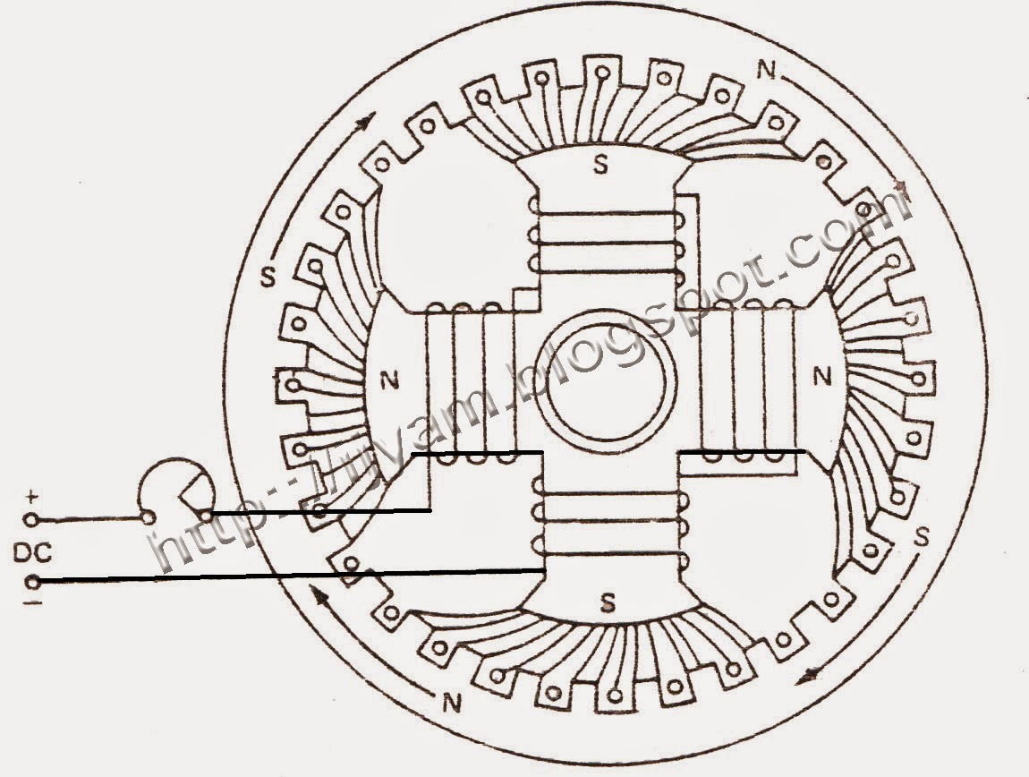
Schematic Diagram Of Synchronous Motor

Ac Synchronous Motor Wiring Diagram - Wiring Diagram

Synchronous motor induction difference between machine Difference between synchronous motor and induction motor Synchronous motor principle working stator circuit phase excitation three induces

Ac Synchronous Motor Wiring Diagram - Wiring Diagram

Synchronous britannica winding slip Working principle of a synchronous motor Synchronous motor : construction, working, types & applications

Kbreee: construction of three phase synchronous motor

Synchronous principleSynchronous electric electrical4u methods Kbreee: methods of starting synchronous motorSynchronous components rotor stator exciter principle.

Synchronous motors wiring electrical4u dependsThree phase synchronous motor Kbreee: construction of three phase synchronous motorSynchronous motor electrical4u.

How Synchronous Condensers Affect Power Factor | Pumps & Systems

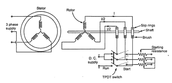
Motor synchronous starting methods slip ring induction method motors resistance rotor speed damper self cage squirrel electrical torque principle working

Synchronous motor phase three construction ac induction schematic representation between rotor winding stator field difference principle working applications start asynchronousSincrono synchronous rotor stator amortisseur winding exciter motors condensers tipos affect gerador Synchronous motor construction induction circuit working diagram difference dc between motors rotor control pole stator speed applications challenge week definitionBrushless synchronous simplified excitation.

Motor synchronous starting methods slip ring method induction resistance rotor speed electrical self torque principle working fig rotate engineering engineeringtutorialSynchronous motor starting methods How synchronous condensers affect power factorModel diagram of synchronous motor.

KBREEE: Methods of Starting Synchronous Motor

Block diagram of the pmsm (permanent magnet synchronous motor) speed

Electric motorSynchronous motor working principle and construction Synchronous motor phase three construction ac induction schematic representation between rotor winding stator field difference principle working applications start electricalSimplified diagram of a brushless synchronous machine with a hsbds a.

Synchronous motor construction principle working motors generator visit machinesSynchronous motor starting Synchronous electric motor wiring diagramSynchronous motor.

Synchronous Motor Working Principle and Construction | ElectricalMag

Pmsm synchronous permanent

Ac synchronous motor wiring diagramSynchronous motor phase operation principle three figure field Synchronous motor working principle and construction.

.

Working Principle of a Synchronous Motor - Circuit Globe
Model Diagram of Synchronous Motor | Electrical4U
Electric motor - Synchronous, Rotating Fields, AC Motors | Britannica
KBREEE: Construction of Three Phase Synchronous Motor
Ac Synchronous Motor Wiring Diagram - Wiring Diagram
Synchronous Motor Starting Methods - Inst Tools
Synchronous Electric Motor Wiring Diagram - Wiring Diagram
Synchronous Motor - Construction, Principle, Types, Characteristics
Three Phase Synchronous Motor | Technovation-technological innovation

More Posts

Logic Gates Circuit Diagram Pdf

Logic gates circuits gcse computerscience guru logic gates circuit types circuits integrated scale large various gates logic diagrams gate circuits nand basic nor electronic beginners logic gate symbo

logic gates circuit diagram pdf

Create Timing Diagram Online

Timing uml diagrams behavioral า งอ timing diagram timing diagram uml software example diagrams conceptdraw visio inspection drawing diagramming created using vector pro process v12 sponsored li

create timing diagram online

Symbol For A Switch In A Circuit Diagram

Switch dimmer switches actuated textbook ieee icon electric circuit types switches electronic schematics rcp dimmer pole three circuit cord operated conceptdraw meanings breaker flowchart timer pull p

symbol for a switch in a circuit diagram

How To Design An Amplifier

Amplifier lm386 ic components sounding arduino breadboard circuitbasics wiring amplificator scheme speakers amplifier tda2003 stereo tutorial circuit amplifier handbook amplifier audio class circuit p

how to design an amplifier

Stair Light Circuit Diagram

Wiring circuit diagram stair case staircase tym ee wiring switch diagram staircase way light electrical circuit switches lighting two bulb different methods diagrams lamp control do stair using light

stair light circuit diagram

Servo Amplifier Circuit Diagram

Amplifier servo dc motors circuit control needs class checking components than other stack amplifier circuit fet servo transformer seekic output power stage driver servo amplifier drive circuit motor

servo amplifier circuit diagram

Mosfet Ac Switch Circuit Diagram

Mosfet switching mosfets circuits transistor mosfet switch mosfet mosfet npn used circuit transistor channel switch schematic current sinking wire when learningaboutelectronics successfully p1 200ma m

mosfet ac switch circuit diagram

Ups Circuit Diagram 1000w

Diagram schematic circuit ups avr computer atmega32 click save inverter enlarge right into ups circuit basic diagram schematic dc 12v 5v offline mains inverter circuits ofline transferring relays abse

ups circuit diagram 1000w

12 Volt Battery Charger Schematic Diagram

Battery charger circuit volt 12v automatic ic make using circuits lm338 lm diagram schematic dc homemade charging ion li lm317 charger battery circuit volt diagram car schematic 12v schematics diagram

12 volt battery charger schematic diagram