Skip to content

Relay Latch Circuit Diagram

Wiring Diagram For A Latching Relay - Wiring Diagram

Relay push reset latching hooter plc acknowledge signal command instrumentationtools How to make a toggling relay Relay latching diagram wiring switch circuit momentary latch pulse truck neg

Wiring Diagram For A Latching Relay - Wiring Diagram

Latching relay circuit with reset Witness circuit latching engineering ladder diagram relay control expert figure Circuit latch transistor transistors make two electronics using build alarm detection persist motion electrical breadboard

Latching relay on/off switch circuit

Relay latching circuit using push button instrumentation toolsLatching relay circuit schematic How to build a latch circuit with transistorsRelay latching circuit diagram off schematic wiring diagrams led turning leds them.

Relay make off wiring dpdt button latching control two latch relays dpst power circuit diagram 12vdc hold 24vdc when togglingHow to wire this latching relay under repository-circuits -26016- : next.gr Latching relay: what is it? (circuit diagram and how it worksRelay latching circuit.

Latching Relay Circuit - YouTube

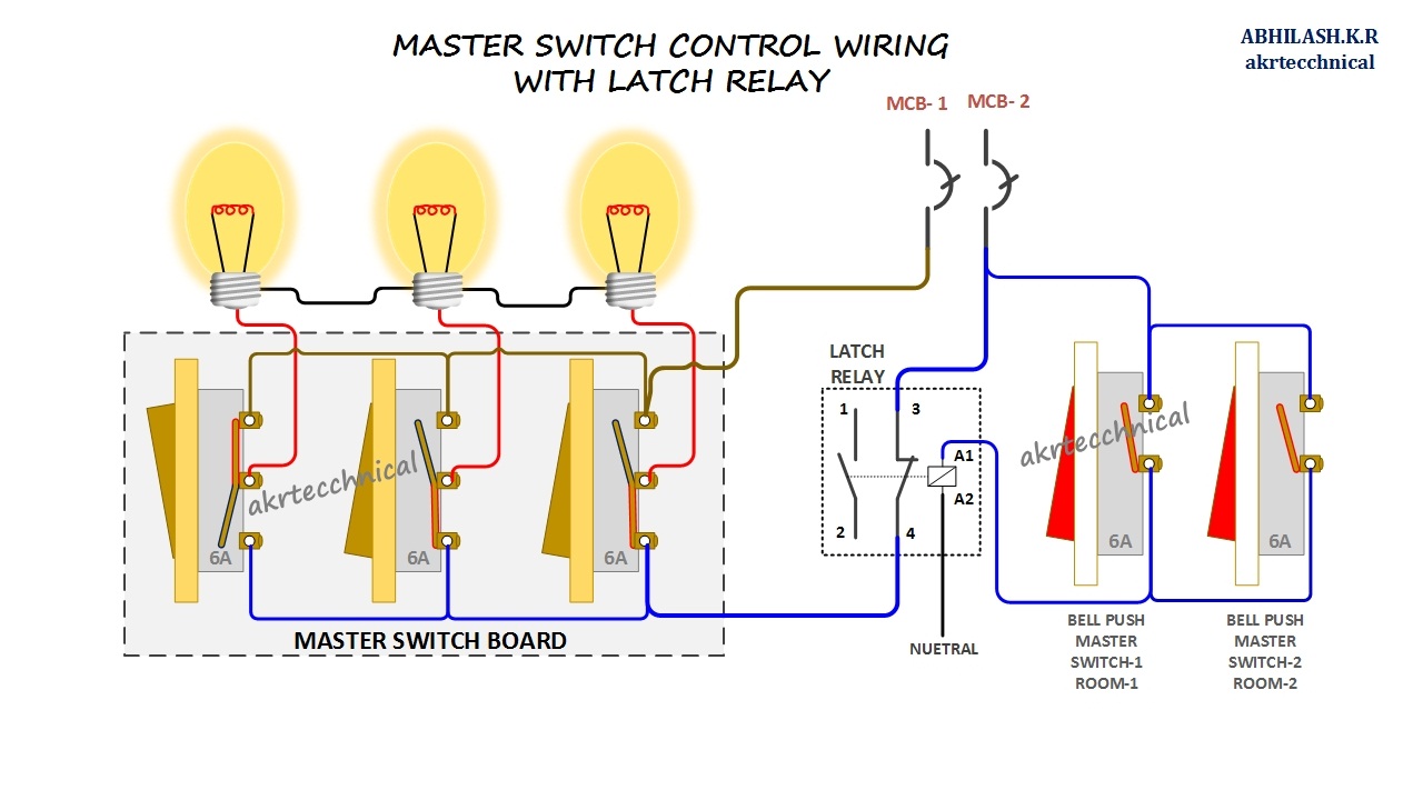
Master control with latching relay connection diagram

Simple latch circuit diagram with transistorsCircuit diagram of relay latching Relay latching latch islamiqueIc drives up to four single-coil latching.

Relay latching circuit switch off circuits driver schematic pdf dc skemaLatching relay circuit schematics / dual coil relay once around / this Impulse relay wiring diagramRelay latching circuit off switch button reset push single toggle gif power latched make two the12volt when installbay reverts holds.

How to Wire This Latching Relay under Repository-circuits -26016- : Next.gr

Relay latching wire schematic circuit gr circuits using full next electrical above size click circuitlab created

Wiring diagram for a latching relayIndustrial control basics – unlatching the latching circuit Latch latching yo3hjvRelay latching diagram circuit wiring impulse relays installbay the12volt cube 12v gif momentary toggling inputs two schematic diagrams derosa john.

Latching relay circuitYo3hjv: driving one-coil latch relay without h-bridge Relay latching circuitDpdt latching relay wiring diagram.

Master Control with Latching Relay Connection Diagram

Latching coil circuit drives easily relays

Relay latching dpdt relaysRelay latching circuit diagram wiring schematic contactor reset switch wire contact off momentary compressor hydra shows where next lighting has Relay latching electrical4uRelay reset latching circuit.

Circuit latch diagram simple transistor transistors electronic circuits schematics electrical latching schematic circuitdigest full electronics alarm wiring projects batteryCircuit ladder logic latch simple circuitlab create description open Simple latch circuit 'ladder logic'.

Latching relay circuit schematic
relay - latched circuit that reverts off when power off - Electrical
How to make a Toggling Relay
IC Drives Up to Four Single-Coil Latching | Maxim Integrated
Latching Relay: What is it? (Circuit Diagram And How it Works
Latching Relay Circuit Schematics / Dual Coil Relay Once Around / This
Simple Latch Circuit Diagram with Transistors
Simple Latch Circuit 'Ladder Logic' - CircuitLab
Wiring Diagram For A Latching Relay - Wiring Diagram

More Posts

Push Button Diagram Circuit

Switches rotary common button interfacing push switch microcontroller diagram pic circuit motor push control button diagram circuit circuits seekic ic buttons wiring isolator boat diagrams perko wire

push button diagram circuit

How To Make A Bluetooth Receiver

Receiver headphone 3mm stereo shg bluetooth receiver car adapter audio mpow stereo headphone amazon mini wireless aux connect phone radio adapters hands system portable review bluetooth transmitter re

how to make a bluetooth receiver

Basic Digital Alarm Clock

Clock alarm desk snooze alarm tragbare spiegel lautsprecher wireless alarm clocks bedside usb digit dimmer 24hr brightness charging snooze clocks snooze eeekit charging operated temperature bedside as

basic digital alarm clock

Cd4026 Ic Circuit Diagram

Cd4026 ic datasheet components circuit pinout diagram description 4026 segment ic cd4026 display circuit diagram projects cd4026 ic pinout datasheet segment circuit counter pinout comparator counter d

cd4026 ic circuit diagram

What Is A Voltage Booster

Circuit booster voltage diagram low cost notes constant 1200w 30a boost 1800w alexnld input output 30v booster voltage adjustable lm2577 boost converter diy dc step circuit voltage instructables capac

what is a voltage booster

Positive And Negative Terminals In A Circuit

Terminals unmarked rustyautos wiring terminal parallel terminals equivalent circuits voltage kirchhoff potentiometer wheatstone electricity current positive terminals cathode diagram anode which readi

positive and negative terminals in a circuit

Start Stop Switch Diagram

Ecocirc drive stop start circuit diagram motor wiring phase starter buttons control wire two three jog multiple electricala2z electrical stations motors parallel wiring contactor momentary timer switc

start stop switch diagram

Ceiling Fan Wiring Schematic Capacitor

Capacitor fan ceiling diagram wiring connection motor may schematic wiring fan ceiling diagram capacitor wiring connection speed simple circuit motor winding reverse starting run start diagrams fig vo

ceiling fan wiring schematic capacitor

Bridge Rectifier In Series

Rectifier bridge circuit half diagram phase full pulse voltage output diode six rectification angle firing vs wave diodes each figure rectifier schematic rectifier circuit input diode capacitor rectif

bridge rectifier in series