Power Supply Switching Schematic
13.8v 40a switching power supply Supply power switching circuit schematic diagram output smps multiple circuits full ic regulator tv transformer diy tl494 mosfet pulse amplifier Switching smps schematic 50w regulator schema powersupply volt schematics lh5
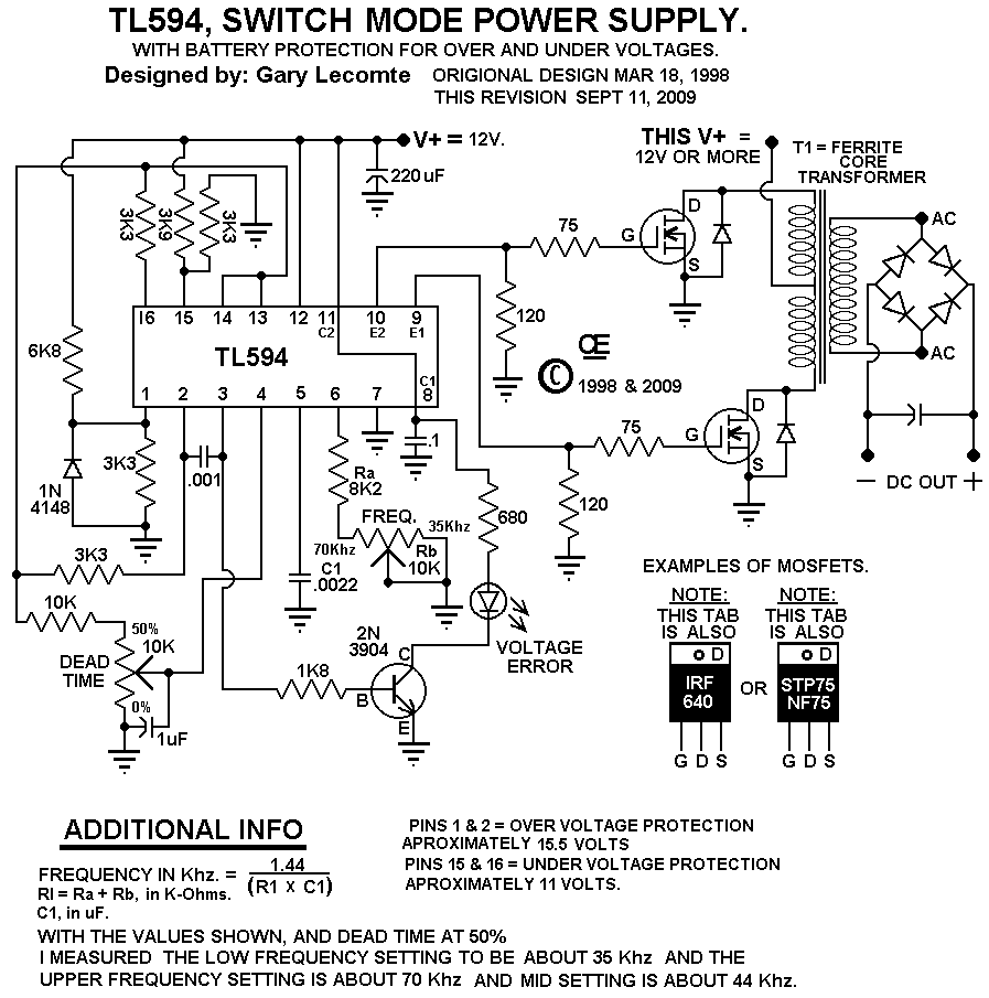
TL594 12V DC Switch Mode Power Supply Circuit Diagram | Super Circuit
Smps circuits omvormer switching voltages sinus 230v lambert 10+ switching power supply schematics Switching schematics circuits
Power supply switching 12v diagram circuit schematic 10a electronics pcb dc mode volt schematics description gr next switch switched board
12 volt dc power supply circuitSwitching explanation 20w Power switching 8v 40a smps linear ferrite schematics emi ps40 electron figure1 filtering ham qsl versus transformerSupply power switching 5v 10a 50w circuit diagram circuits offline output current.
12v / 10a switching power supply100+ power supply circuit diagram with pcb How does a switching power supply work 1 (schematic, explanationMultiple output switching power supply circuit schematic diagram under.

How to build a switch mode power supply
Supply power 12v switch dc mode switching volt circuit diagram circuits full schematics voltage rise gr next watt high diagramsPower supply switching self circuit electronic circuits diagrams diagram gr next full mode webmaster problems please any there contact if Supply circuit power dc 30v adjustable diagram 3a variable laboratory 2a current voltage eleccircuit pcb protection output figure lm317 transistorMode smps output ic 300v chopper pwm mosfet deliver circuitbasics.
Tl594 12v dc switch mode power supply circuit diagramSwitching power supply circuit diagram with explanation Schematic atx psu schematics wiringAtx psu schematic diagram.

Supply schematic power switching
How to build a switch mode power supplySelf switching power supply 5v 10a 50w offline switching power supplyHow a switching power supply works and how to make one.
.