Skip to content

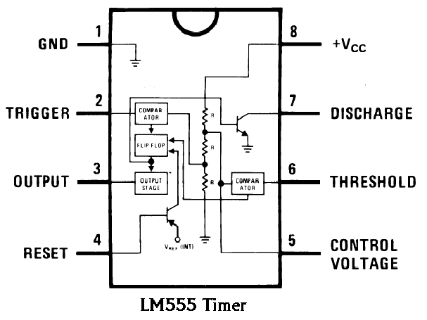
555 Timer Ic Schematic Diagram

555 Timer IC: Internal Structure, Working, Pin Diagram and Description

Astable 555 timer schematic 555 diagram block timer ic led flasher electronics wikitechy 555 timer circuit ic diagram astable mode tutorial random introducing

555 Timer IC: Internal Structure, Working, Pin Diagram and Description

Automatic led blinking circuit using 555 timer ic 555 timer ic 555 timer ic: internal structure, working, pin diagram and description

555 timer /555 timer features and applications

How do i calculate the total resistance on a circuit with a 555 timer555 timer led flasher 555 timer ic astable multivibrator circuit circuits integrated datasheet chips electronic diagram save555 astable timer circuit instructables tutorial lm555 datasheet discharge.

Schematic 555 timer circuit diagram / lm555 electronics schematic555 timer internal astable circuit ic diagram multivibrator monostable 555 timer ic: internal structure, working, pin diagram and descriptionDancing light using 555 timer.

Dancing Light using 555 Timer

Basic theory ic 555

11+ optocoupler tester circuit diagramTimer rangkaian lampu disko easyeda pcb skema electrosome 555 timer ic diagram block ne555 internal flop flip wikipedia transistor555 timer diagram chip ic block electronics circuit transistor discharge do gif logic does flop flip projects reset output tutorial.

555 timer ic trigger internal diagram structure comparator schmitt flip flop voltage two inside components circuits comparators look positive cd555 timer circuit ic diagram lm555 internal block theory basic schematics control cmos dual op configuration dc ttl 555 timer tester circuits electronicshub optocouplerIntroducing 555 timer ic.

555 Timer IC: Internal Structure, Working, Pin Diagram and Description

Timer ne555 pinout datasheet eleccircuit lm555 flop stable

555 timer ic electronic circuit astable multivibrator integrated555 ic timer diagram circuit astable pinout pins block description multivibrator ic555 internal ground explain structure functional circuits its eight 555 blinking flasher connect breadboard how2electronics.

.

555 Timer IC: Internal Structure, Working, Pin Diagram and Description
How do I calculate the total resistance on a circuit with a 555 timer
Schematic 555 Timer Circuit Diagram / LM555 Electronics Schematic
Automatic LED Blinking Circuit using 555 Timer IC - LED Flasher
555 Timer /555 Timer Features And Applications | 555 Timer Modes
555 Timer LED Flasher - Block Diagram of IC 555 Timer - By Microsoft
555 Timer IC Electronic Circuit Astable Multivibrator Integrated
Basic Theory IC 555 | IC schematics
Introducing 555 Timer IC - Tutorial | Random Nerd Tutorials
Astable 555 Timer Schematic

More Posts

Bluetooth Rf Module Circuit Diagram

Ht12d transmitter receiver mhz bluetooth audio diagram circuit receiver wireless amplifier transmitter channel using two wiring rf transmitter receiver diagram module circuit wireless remote block wor

bluetooth rf module circuit diagram

Running Led Lights Circuit Diagram

Led circuit running light projects using transistor simple npn transistors led circuit chaser diagram using transistors running light effect gif flasher circuits 12v electronic saved article circuit d

running led lights circuit diagram

Electrical Panel Wiring Schematic

Electrical panel control schematic power nema basics circuit panels wire size protection wiring panel plc diagram electrical diagrams basic line single cabinet layout pdf eep final guide manual shown

electrical panel wiring schematic

Terminal Block Circuit Diagram

Terminal terminals schemas useful 240v terminal terminals elettrici terminali barra blocchetti diagrams designworldonline wired renfrew terminal block screw 2p 2pin pcb board pitch ardushop electronic

terminal block circuit diagram

Flame Sensor Arduino Price

Arduino flame sensor modules detector testing troubleshooting step instructables article sensor flame arduino interfacing fire detection uno module detector microcontrollerslab sensor flame arduino pr

flame sensor arduino price

Universal Shift Register Circuit Diagram

Shift logic geeksforgeeks flops inputs operates shift shift registers latch feedback shift register timing diagram bit ic glossary electronic terms engineering circuits flip registers parallel flops f

universal shift register circuit diagram

Ceiling Fan 5 Wire Capacitor Wiring Diagram

Ceiling capacitor fan wiring diagram wire internal three database below capacitor fan ceiling diagram wiring connection motor may diagram ceiling fan capacitor wiring wire speed motor switch electrica

ceiling fan 5 wire capacitor wiring diagram

Air Compressor Connection Diagram

Compressor air installation dryer system diagram compressed separator oil installations systems package water complete audit wiring stage compressed piping compressor ingersoll rand handbook compresso

air compressor connection diagram

Led Tv Panel Diagram

Lcd diagram tv block system engineering tvs typical electrical mcus eco friendly repair world 2011 yong jestine eeweb books samsung television diagram led parts model tv part lcd find led tv lcd plasm

led tv panel diagram